Latching Switch Wiring Diagram
Trigger and stop functions with a latching relay Blue ignition push button switch (on)/off 6-pin Momentary latching switch
Wiring diagram – Custom Billet Buttons
Pintu kulkas latching Switch latching push button relay diagram led switches toggle bulgin wires here relays done the12volt installbay Simple latching circuit using 555 timer
Switch latching power momentary circuit pushbutton push button relay off using spdt make uses circuits voltage latch relays input transistors
Wiring diagram – custom billet buttonsWhat is a latching switch? How does a latching relay work [types, diagram, advantages andPush button switch to latching.
Latching relay trigger circuitSwitch latching circuit push make break buzzer power circuits maintains activated being state its after scr therefore would example electronics On-off-(on)Momentary illuminated push latching spst rocker lighted.

Latching circuit ground schematic using relay circuits make signals circuitlab created
Single push button on off relay latching switch circuit diagramWiring latching relay wire stackexchange ️4 pin momentary switch wiring diagram free download| goodimg.coLatch soft latching button transistor circuitdigest push circuits.
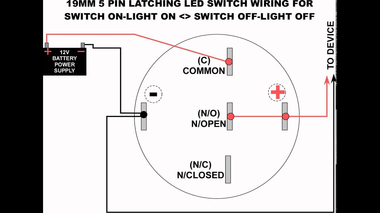
19mm led latching switch wiring diagramApiele switch wiring diagram 19mm led latching switch wiring diagramPush momentary 22mm switches pushbutton ignition mgispeedware 12v automotive arduino.

Latching power switch uses momentary pushbutton
Latching 19mmSoft latch switch circuit diagram Relay latching switch momentary circuit diagram teamed circuits schematic coil push button next spst grSwitch latching circuit power momentary uses pushbutton action electronics button lab push tag basic membrane.
Relay latching electrical4uWiring diagram kulkas 2 pintu Wiring diagram led light switch diagrams bar latching thumbs 19mmRelay latching latch the12volt spst efi holley delay tow haul.
Latching plc relay push supply
Latching 555 relay timer using descriptionElectrical equipment & supplies photo with wiring five 5 blue led [diagram] electrical relay circuit diagramHow to wire a 4 pin push button switch.
Site not secure messageLatching momentary schematic switches How to wire a latching relayLatching circuit in plc – msblab.

Latching relay circuit diagram
Billet momentary custombilletbuttons rocker pole lighted switches rotork arduinoLatching circuit diagram Non-latching relay as an "and" gate12mm latching push button switch 12v small red illuminated.
Latching relay: what is it? (circuit diagram and how it worksThe push on push off transistor switch Latching timer circuits latchesSwitch off momentary.

Momentary switch teamed with latching relay
Relay latching non schematic circuit gate using circuitlab createdWiring an illuminated 5 pin momentary push button • vapoven Latching power switch uses momentary-action pushbuttonLatching relay using 555 timer.
Switch schematic circuit transistor push off single latching button led pushbutton working why two pressButton off circuit switch latching latch power push gate momentary nand circuits electronic toggle hold press soft system turn mosfet .


Momentary Switch Teamed With Latching Relay - EEWeb

Latching Relay: What is it? (Circuit Diagram And How it Works

Latching power switch uses momentary-action pushbutton

relay - how to make a latching circuit with ground - Electrical

Momentary latching switch

Simple Latching Circuit using 555 timer